| News | Date:2020-8-15 Publisher:Sumino Precision |
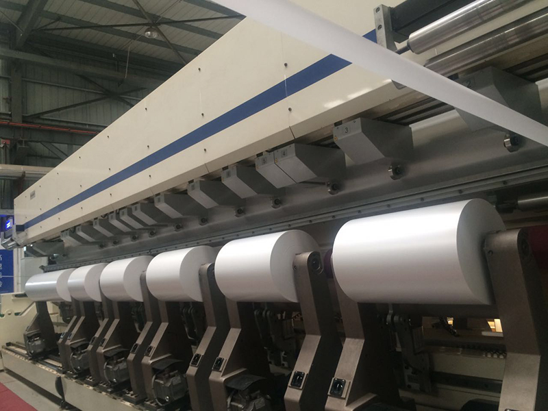
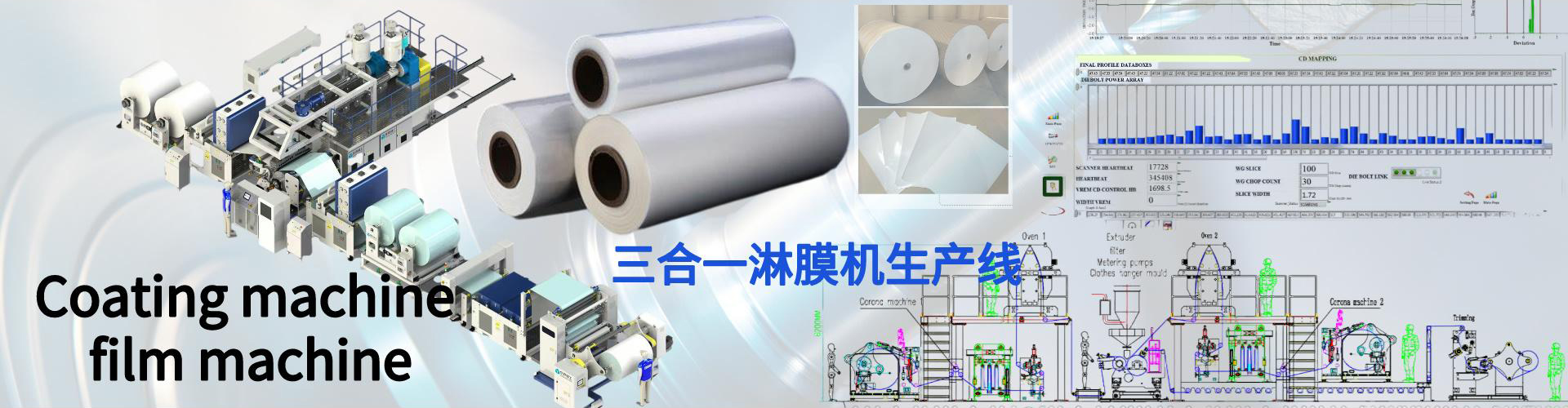
Release paper coating machine production line
The utility model relates to a production line, in particular to a release paper coating and laminating production line.
Background technique :
Release paper, also known as release paper, release paper, and silicone oil paper, is a release paper that prevents the prepreg from sticking and protects the prepreg from contamination. Most of the materials are produced separately in the process of processing, which requires a waste of time and manpower. Repeated handling, and due to the different production environments of various manufacturers, and cost problems, most manufacturers use ordinary workshops, which have much poorer environmental cleanliness, which affects the production quality of paper.
Technology realization elements:
The technical problem to be solved by the utility model is to overcome the defects of the prior art and provide a release paper coating and film production line, which uses a compact structure to make materials from film coating, coating, drying and cutting into an integrated shape, and conveys them by a conveyor belt. Reduce transportation time and labor costs, and re-use the retractable dust cover, you can choose to shield and protect the machine as needed to reduce the entry of dust, and use a temperature monitor to maintain a constant temperature for drying to improve production safety.
In order to solve the above technical problems, this utility model provides the following technical solutions:
The utility model relates to a release paper coating and laminating production line, which includes a discharging area. The top of the discharging area is provided with a rail, the top of the rail is provided with a telescopic cover, and one side of the rail is provided with an engine, One side of the discharging area is provided with a coating area, one side of the coating area is provided with a coating area controller, a hopper is provided at the top of the coating area, and one side of the coating area is provided There is a coating zone, one side of the coating zone is provided with a coating zone controller, one side of the coating zone is also provided with a dryer, and the bottom end of the dryer is provided with a support frame, so A number of exhaust pipes are provided on the outside of the dryer, a conveyor belt is provided inside the dryer, a receiving rack is provided on one side of the dryer, and a cutting machine is provided on one side of the receiving rack , A storage area is provided on one side of the cutting machine.
As a preferred technical solution of the utility model, the discharging area, the coating area and the coating area are all provided with retractable covers.
As a preferred technical solution of the utility model, a temperature controller is provided in the dryer.
As a preferred technical solution of the utility model, the discharging area, the coating area and the coating area are connected in transmission.
Compared with the prior art, the beneficial effects of this utility model are as follows:
The utility model makes use of the track to facilitate the expansion and contraction of the cover in the discharge area, the coating area and the coating area. It does not occupy space and protects the production process to reduce the generation of dust. It prevents the product from being affected. The quality of the machine is compact. The film is re-coated to make the printing and dyeing effect of the product better, and the conveyor belt is used to convey the output, which reduces the floor space and saves the time and labor of transportation. The temperature controller in the dryer maintains the control of the temperature in the dryer to prevent Misfire caused by improper operation.
Figure Description
The accompanying drawings are used to provide a further understanding of the utility model and constitute a part of the specification. Together with the embodiments of the utility model, they are used to explain the utility model and do not constitute a limitation to the utility model. In the attached drawing:
Figure 1 is one of the structural schematic diagrams of this utility model;
Figure 2 is the second structural diagram of the utility model;
In the picture: 1. Unwinding area; 2. Laminating area control machine; 3. Laminating area; 4. Hopper; 5. Coating area; 6. Exhaust pipe; 7. Conveyor belt; 8. Support frame; 9. Material receiving rack; 10, cutting machine; 11, storage area; 12, track; 13, telescopic cover; 14, engine; 15, coating zone controller; 16, dryer.
The yellow release paper is unrolled in a double position, after passing through a special oven tunnel, oiled and dried, then through the extruder to melt the PE polyethylene on-line compounding, and then through the winding.